
The equations of heat transfer have not changed. The density, speed, interfaces, and consequences have.
The familiar heat balance—and the new boundary conditions
Every data-center cooling discussion eventually returns to the same first principle: electrical power entering the IT equipment becomes heat that must leave the building. The physics is familiar. What has changed in the AI era is the intensity of the heat, the concentration of the load, the speed at which it changes, and the number of engineering interfaces between the chip and the atmosphere.
For years, the dominant question was: how do we deliver enough conditioned air to the front of the rack without mixing it with hot exhaust? Today, that question still matters, but it is no longer sufficient. The design team must also ask how much heat is captured at the silicon, what remains in the air, how the technology cooling system connects to the facility water system, what happens during a pump or controls failure, and whether the rejected heat is a liability or a resource.
The traditional era: the room was the cooling machine
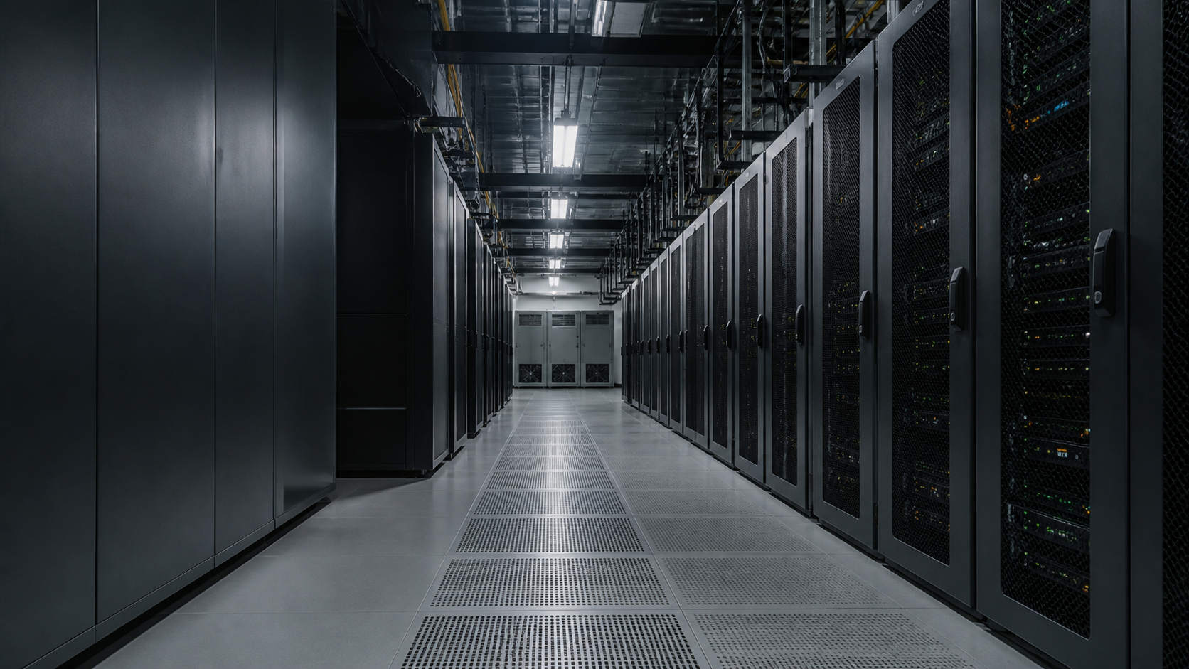
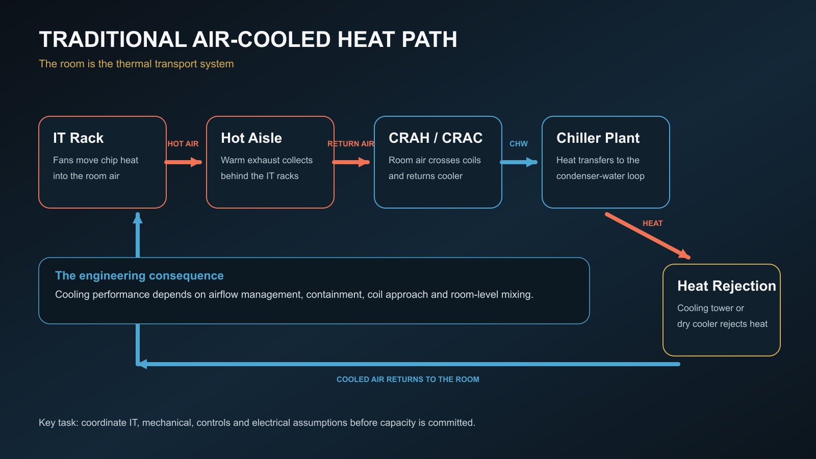
The conventional air-cooled data center is an elegant chain when each link is kept under control. Server fans move room air through heat sinks. Hot exhaust is collected in an aisle or ceiling return. A CRAH or CRAC removes heat from the air. Chilled water or refrigerant carries it to a chiller, economizer, dry cooler, or cooling tower. The cooled air returns to the white space and the cycle begins again.
This architecture is mature, widely understood, and highly serviceable. With effective aisle containment, blanking panels, pressure management, sensible temperature setpoints, and disciplined commissioning, it can be remarkably efficient. DOE guidance continues to treat air management, economization, optimized water temperatures, and heat recovery as foundational measures.[2][3]
But air has a cost. Moving more heat means moving more air, overcoming more pressure drop, and accepting larger temperature differences. Once rack density climbs, small defects become expensive: a missing blanking panel becomes recirculation; excessive underfloor pressure becomes bypass air; a cable opening becomes a short circuit between supply and return; an apparently safe average temperature hides a local inlet excursion.
The AI era: cooling moves toward the silicon
AI infrastructure changes the problem because it concentrates large, sustained compute loads into rack-scale systems. ASHRAE's AI data-center framework describes purpose-built AI facilities where rack densities routinely exceed roughly 50–120 kW and may trend higher, making technology cooling systems central to the thermal architecture.[1] NVIDIA's GB200 NVL72 is one visible example: 72 GPUs and 36 Grace CPUs are integrated into a rack-scale, liquid-cooled system.[4][6]
At this level, cooling cannot be treated as a background utility selected after the IT layout. The mechanical design, electrical design, rack architecture, controls, deployment sequence, and operating model become one coordinated system. If power is planned without coolant distribution, or coolant distribution without service clearances and isolation strategy, the project is already carrying avoidable risk.
Direct-to-chip liquid cooling: what the flow path actually does
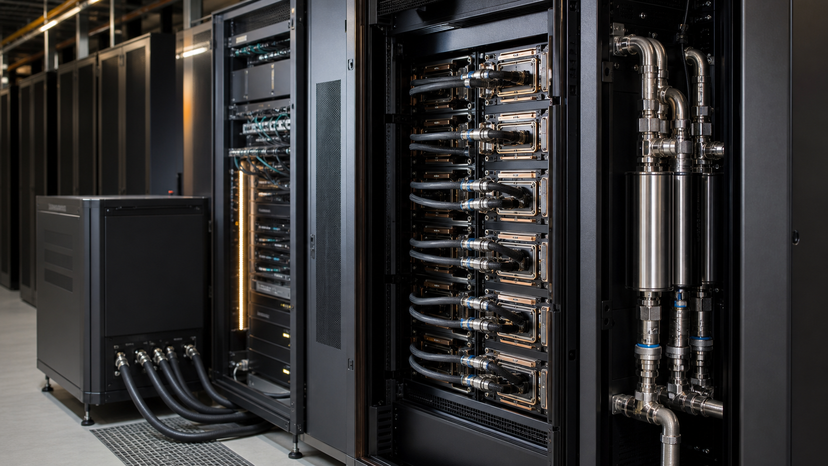
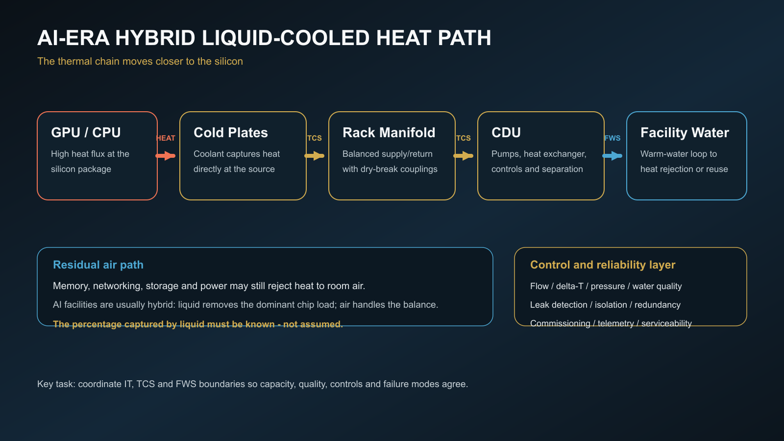
In direct-to-chip cooling, cold plates sit on high-heat-flux components such as GPUs and CPUs. A technology cooling system (TCS) circulates coolant through server hoses and rack manifolds. A coolant distribution unit (CDU) provides pumping, filtration, controls, and usually a liquid-to-liquid heat exchanger. On the other side, the facility water system (FWS) carries heat toward dry coolers, cooling towers, chillers, economizers, thermal storage, heat recovery, or a combination of them.
That separation matters. The TCS has technology-specific requirements for chemistry, cleanliness, materials compatibility, pressure, flow, temperature, and allowable transients. The FWS has building-scale requirements for redundancy, water treatment, heat rejection, and climate response. The CDU is not merely a box between them; it is a hydraulic, thermal, controls, and risk boundary. OCP's dedicated CDU work reflects how important that integration has become.[5]
Why the AI data hall is usually hybrid—not liquid-only
The phrase ‘liquid-cooled rack’ can create a dangerous simplification. Cold plates may capture most of the GPU and CPU heat, yet memory, storage, networking, power supplies, busbars, and other components may continue to reject heat to air. NVIDIA's rack documentation describes liquid cooling for cold-plated CPUs and GPUs while other components remain air cooled.[4]
This residual air load determines whether the room still needs CRAHs, fan walls, in-row units, or another air system; how much redundancy those systems require; and whether the rack vendor's fan curves agree with the facility pressure regime. The design team needs an explicit heat-capture ratio at each operating condition. ‘Liquid cooled’ is not a calculation.
Liquid cooling is not a shortcut around engineering
Liquid carries heat efficiently, but it also brings failure modes that traditional operations teams may not yet own. Reliability depends on disciplined details: material compatibility, coolant chemistry, filtration, degassing, pressure control, hose routing, bend radii, dry-break selection, dripless service procedures, leak detection zoning, isolation valves, pump redundancy, sensor calibration, and alarm rationalization.
Hydraulic balance deserves particular attention. Parallel racks do not automatically receive equal flow. A low-resistance branch can starve a remote rack; a control valve can hunt; a dirty strainer can quietly move the operating point; a CDU sized on peak capacity can behave poorly at minimum turndown. The cure is not one oversized pump. It is a verified system curve, stable control authority, measurable rack flow, sensible differential-pressure management, and commissioning across the complete operating envelope.
The same discipline applies to redundancy. N+1 equipment counts are not enough if a common control panel, header, strainer, heat exchanger, water-quality event, or maintenance isolation can defeat the redundant path. Resilience is a sequence of events, not a label on a schematic.
Efficiency: do not optimize PUE in isolation
Direct liquid cooling can reduce server and room fan energy and support warmer coolant temperatures, expanding economizer hours or allowing dry heat rejection in suitable climates. DOE guidance also highlights the value of higher leaving-water temperatures for heat recovery.[2][3] But no technology is automatically sustainable.
A low PUE can coexist with high water use, poor grid carbon intensity, weak server utilization, or rejected heat that could have displaced another fuel. AI-era thermal strategy should therefore be judged with a family of metrics: PUE for total facility energy, WUE for water, CUE for carbon, cooling-system efficiency, and—where a real heat customer exists—energy reuse effectiveness. The best answer is climate- and site-specific.
Warm-water loops create an important opportunity: the closer the return temperature is to a useful heating temperature, the more practical heat reuse becomes. Yet recovery only works when a nearby consumer needs the heat at the right time, temperature, and reliability level. The data center still requires a complete independent heat-rejection path.
A practical decision spectrum
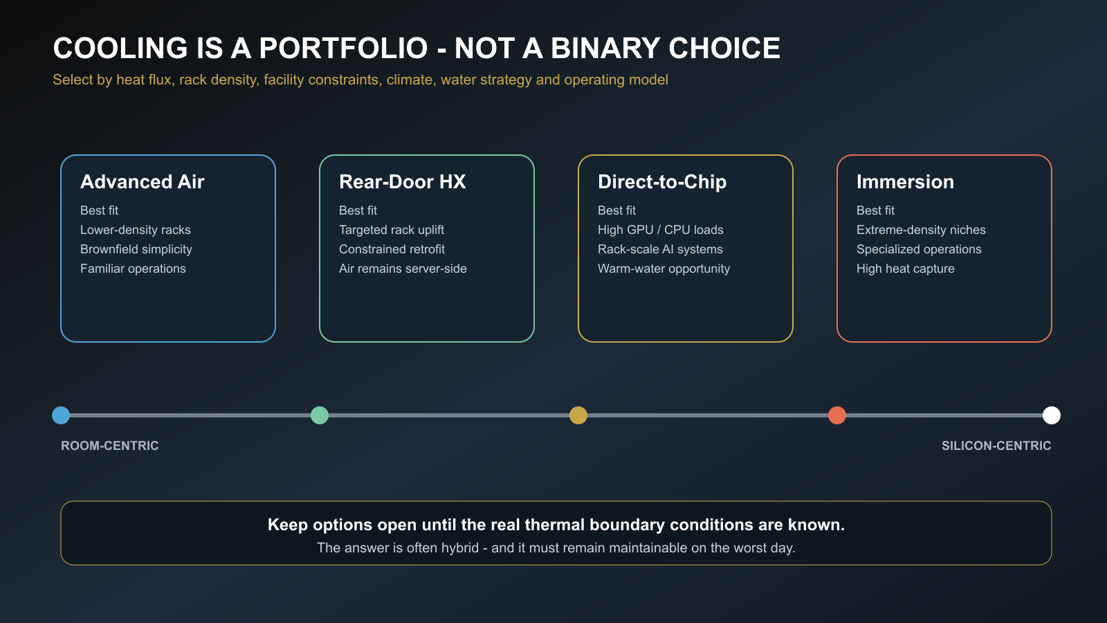
Air versus liquid is the wrong first question. The useful question is: which combination of technologies creates the most reliable and efficient heat path for this workload, building, climate, water strategy, and operating team?
Advanced air remains a strong choice for lower-density racks and many brownfield estates. Rear-door heat exchangers can provide targeted density uplift while keeping liquid outside the server. Direct-to-chip cooling is increasingly central to rack-scale AI. Immersion can serve specialized extreme-density or harsh-environment applications, but it changes hardware service, fluid handling, and supply-chain assumptions. The answer is often hybrid.
Retrofit planning
Seven questions before converting an existing data center for AI
- 01
What is the real load profile?
Confirm rack power, diversity, ramp rate, sustained training load, inference variability, and future generations—not only a nameplate total.
- 02
How much heat is captured by liquid?
Obtain component-level heat rejection to liquid and air for normal and degraded states.
- 03
Can the building distribute coolant?
Check risers, pipe routes, structural loads, service corridors, drainage, leak zones, valves, and phased connections.
- 04
Can the heat-rejection plant use warmer water?
Model climate bins, economizer hours, dry versus evaporative rejection, chiller lift, water use, and heat-reuse potential.
- 05
Are electrical and mechanical growth aligned?
A rack cannot be energized safely before its cooling path, controls, detection, and redundancy are commissioned.
- 06
Who owns each interface?
Define responsibility across the IT vendor, rack integrator, CDU supplier, controls contractor, mechanical designer, and operator.
- 07
How will the system fail and recover?
Test pump loss, valve failure, control loss, leak detection, power transfer, maintenance isolation, restart, and workload response.
The deeper lesson
Cooling is no longer a background mechanical service that follows the IT design. In the AI era, thermal architecture determines how much compute can be installed, how consistently it performs, how quickly it can scale, how much energy and water it consumes, and how gracefully it responds when something goes wrong.
The most successful projects will not be those that simply add liquid cooling. They will be those that connect chip, rack, CDU, facility water, heat rejection, controls, and operations into one measurable, maintainable system. That requires the habits mechanical engineers already know: define the boundary conditions, build the heat balance, model the flow, test the failure modes, commission the controls, and leave the operator with a system that can be understood at 2 a.m.
Preparing for higher-density infrastructure?
Share the constraint you believe the industry is underestimating—or bring Stravex the thermal question your project needs to resolve.
References
Sources and further reading
- [1]ASHRAE, AI Data Center Energy Performance Framework—Energy and Thermal Efficiency
- [2]U.S. Department of Energy, Best Practices Guide for Energy-Efficient Data Center Design (2024)
- [3]U.S. Department of Energy, Cooling Water Efficiency Opportunities for Federal Data Centers
- [4]NVIDIA, DGX GB Rack Scale Systems User Guide—Hardware
- [5]Open Compute Project, Coolant Distribution Unit Sub-Project
- [6]NVIDIA, Blackwell Architecture and GB200 NVL72
All photographs, cover artwork, and flow diagrams were created specifically for Stravex Engineering. No third-party watermarked images were used.